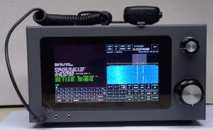
The sBitx is a 25 watts, high performance SDR that you can easily build, it has all popular digital modes like FT8 integrated. This is a blog that gathers all the help, tips, modifications and information about this little radio.
The sBitx is a 25 watts, high performance SDR that you can easily build, it has all popular digital modes like FT8 integrated. This is a blog that gathers all the help, tips, modifications and information about this little radio.
The macros of the sBitx makes it very handy for users to transmit frequently shared information during an exchange such as signal reports or the operator’s QTH and operating setup. These macros are mapped to the function keys and allow the operator to quickly transmit information.
The macros automatically fetch certain inputs like the user’s callsign, grid locator (from initial setup), signal report and the other stations callsign(from the logger) and inserts it in the transmission, according to the format of the macro.
To setup macros, navigate to the /home/pi/sbitx/web folder. Here you will find the macros stored in .mc files. Simply open the files in a text editor, make the required changes and save the files. Fire up the sBitx application and either use the on-screen keyboard or a physical keyboard to send out the macro messages by simply using the F1-F12 keys. The user can choose to stop transmitting the macro at any point by hitting the escape key on the keyboard.
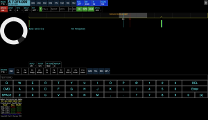
When using the web interface to operate the radio, a macro selector box appears near the on-screen keyboard. This can be used to select a different set of macros, like the macros set for the CQWW CW contest. The user can also create a custom set of macros by simply duplicating an existing file, editing it to suit their need and saving it under a different name.
The sBitx comes equipped with a remote interface that can be accessed via any web browser on any device connected to the local network and allows you to control and transmit from a local machine.
To use the web interface:
The sBitx, out of the box, has some time offset built into the software.
Here is the procedure to get the time in sync.
Here is a printable version of the sBitx user manual.
Please note that the user manual is still under development. Please reach out to support (at) hfsignals (dot) com to report any errors or to share any suggestions.
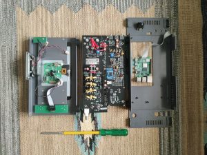
Using a Phillips head screwdriver, remove the indicated front panel screws on the top and bottom.
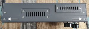
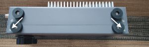
Gently lift the front panel to make sure not to damage any of the wires inside.
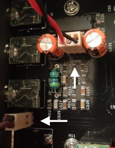
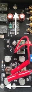
Unplug the microphone and speaker connector on the left hand side of PCB, near the Earphone, Microphone and Key jacks. These require very little force and can be undone by hand or tweezers.
Remove the flat ribbon cable on the pub, under the Raspberry Pi. Next remove the screen power connector, near the RTC module.
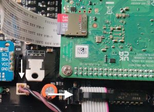
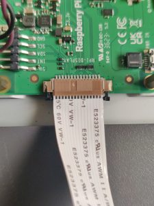
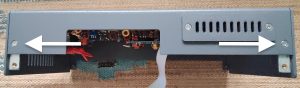
Remove display cable on the display, using a toothpick or a tweezers to undo the cable lock mechanism on both sides by gently nudging the black clip. Be careful not to fold the cable!
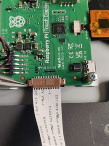
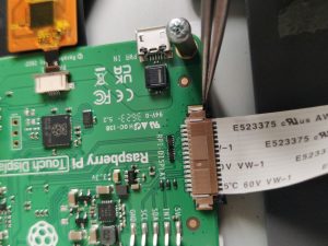
If done correctly, the latch should be released as seen in the photo and the cable should slip out easily.
 Now you can access the Raspberry Pi and the other modules. Proceed further only if you plan to remove the PCB from the enclosure.
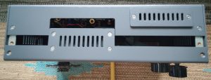
6. Remove power switch connector and remove the indicated back panel screws on the top and bottom. Skip this step if you’re trying to replace the Raspberry Pi, but remove the top and bottom screws of the right side panel.
7. Remove the four screws securing the raspberry pi. Gently nudge the pi out. You could use a finger under the ethernet port to help the Pi out of it’s connector.
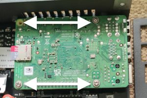
8. Remove the five indicated screws that secure the main PCB.: Two near the BNC connector, one under the Pi, one near the earphone jack and the final one near the power switch.
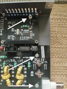
9. After the last screw in removed, the board can be gently removed by sliding it out at an angle. You can also loosen the Pi’s display port cover for better access.
 10. To put everything back together, follow this guide in reverse.
Here is a link to the Raspbian OS image that ships with the radio, in case you need to do a fresh install of the OS.
https://drive.google.com/file/d/1T0cUdQjLZ-0lBFqwywaNBh3rToGb4UJ3/view?usp=drive_link
The image will work with DE, V2, and V3 units.
It is recommended to backup your files in the sbitx/data and sbitx/web folders so that you don’t lose your logbook, calibration, and user settings.
To write the image file to an SD card:
This a document of the current process of testing the sBitx before they are shipped. From 1st May, 2023 onwards, all the sBitxs shipped will carry the test report.
Do not try this at home. You will need a dummy load and an oscilloscope with 50 MHz bandwidth and a signal generator to try it by yourself.
1 The power supply should be on 13.8v, connect mic, and key paddle
2 Set Antuino (signal generator) to 7035, set the wweep 1 KHz to be 1 KHz wide. The signal source should be from another power supply to prevent signal leakage via power cables.
3 Connect Antuino to the other side of the dummy load with at least 60 db Attenuation (50 ohms in series with 100K resistor).
4 A PC/laptop and the sbitx to an ethernet hub before switching on the radio.
5. Set the Oscilloscope, to 200 uSec/horizontal division, 20v/vertical division rang. Connect the probe across the dummy load.
1. Initial test
1 Switch on the set,
2 Connect dummy load, oscilloscope, other side of dummy to antuino
3 Power on the radio
4 ssh into the radio, they default userid is pi and the password is hf12345
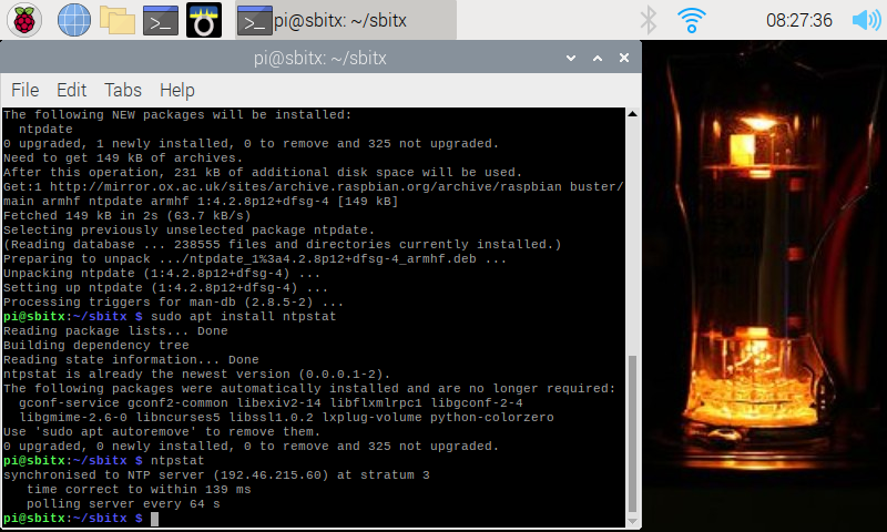
5 run ntpstat, if not synchronized, run
sudo apt install ntp
sudo apt install ntpdate
sudo ntpdate -u time.nist.gov
Type ntpstat until it says the time is synchronized
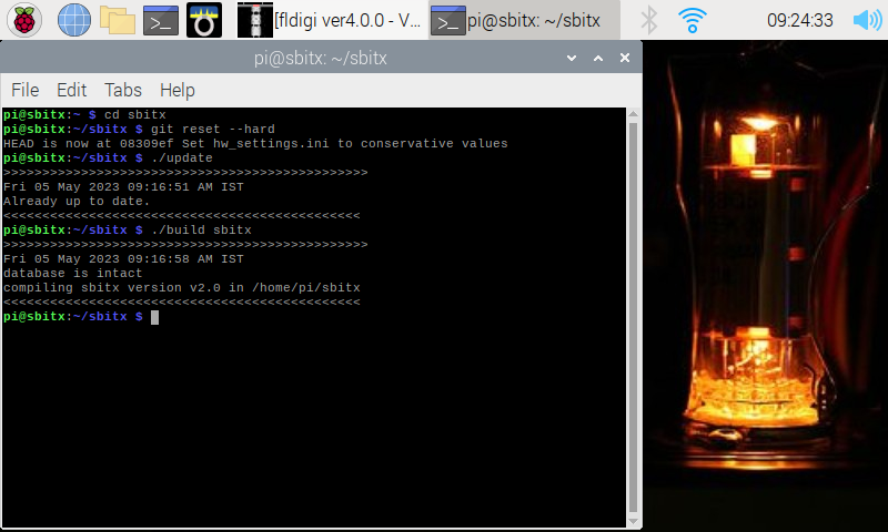
6 get the latest version of sbitx from the github
git reset --hard
 ./update
 ./build sbitx
7 Note the DC Idling current, start sbitx from the ssh command line
8 Check that the RTC clock is detected (look for the message in the Terminal window)
9 Check that the RTC clock is synchronized (this needs active internet) (look for the message in the Terminal window)
10. Note the DC current consumption of the radio in receive mode.
1 Tune the Antuino/Signal generator to 7035
2. set RF gain to maximum
3 Set frequency of sbitx to 7035,
4. AGC OFF
5. Is the noise grass visible yes/no
6. Note the signal level on the spectrum display. Each horizontal division is 10 dB. What is the Antuino sweep level above the noise floor? The -65 dBm signal from through the dummy load should still be at least 60 dB above the noise floor.
8.9 Check the earphone audio of sweep. The audio should be clear and distortion free.
1 Set Mode toUSB
2 Set Mic to 1
3 Set Drive to 1
4 Set PA_BIAS1 preset to zero (fully counter-clockwiseBias)
5 Note DC current on PTT
6.. Slowly increase the bias current until the total current consumed by teh radio is increased by approximately 250 mA.
We first check to see if the bridge is already calibrated and if it isn’t we will proceed with the calibration
1 Set Mode to CW
2 Set Freq to 7035 KHz
3 Set CW INPUT to straight key
4 Set Drive to 1
5 Press the PTT and increase the drive gradually to bring up to the RF voltage on the across the dummy to load to read 125 v peak to peak (or, 62 volts peak).
6. Check the power reading on sbitx screen. If power is between 35 and 45 watts, skip the Part B
PartB : Setting the SWR bridge to correct reading
7. Open console panel
8. Enter “metercal” (DO NOT TOUCH ANY OTHER CONTROL ON SCREEN)
9. Press PTT, note that the output as shown on the oscilloscope is still between 120v and 130 v peak to peak RF
10 Adjust function knob until the power reading is 40 watts on sbitx screen.
11 Press the function knob once, change the mode to trigger saving the configuration.
1 Keep the dummy load inserted as before, with the oscilloscope probe connected across it.
2 Open the sbitx console panel
3 Enter “txcal”
4 Watch the screen show the power being gradually increased to the correct levels on all bands
6 Delete the wifi connection or take off the ethernet
7. Switch off the sBitx and switch it back again for the next test (two tone test)
1 Select MODE 2TONE
2 Set frequency to 7035
3 Set Drive to 100
4 Press PTT
5 See the oscilloscope for perfect shape, (no flat top, no underflow)
6. Power output
7 Measure the output with Drive 100 on all bands, on each band. To prevent aliasing perform all transmit tests at 35 KHz from the band edge.
Check that the RTC time on sbitx screen is same as utctime.net (on phone)
1 Set mode to USB,
2 Mic gain to 25,
3 Frequency on 7043 freq
4 Speak into the mic, note the peak voltage
5 Remove mic
6 Set mic gain to 50
7 Speak into the mic and note the RF
8. From settings panel, Change mode to cw, cwinput to Iambic paddle
9. Test dots and dashes
The latest version of the sBitx software is always on github.com. The easiest way to get this is use the update script and rebuild the sBitx. Here is how :
Open a terminal by clicking Terminal Icon from the top bar. Another way to open the Terminal is to Hold Ctrl and Shift down together and press T.
In terminal, type:
pi@sbitx:~ $cd sbitx
pi@sbitx:~/sbitx $./update
pi@sbitx:~/sbitx $./build sbitx
Here is what it will look like (the exact output from git pull maybe different, depending upon the version you are pulling from github):
The May 4th, 2023 update fixed many things. This post describes how to update the sBitx with these updates.
You can still proceed to the next steps even if the RTC is not working properly.
The latest version of the sBitx software is always on github.com. The easiest way to get this is use the update script and rebuild the sBitx. Here is how :
Open a terminal by clicking Terminal Icon from the top bar. Another way to open the Terminal is to Hold Ctrl and Shift down together and press T.
In terminal, type:
pi@sbitx:~ $cd sbitx
pi@sbitx:~/sbitx $./update
pi@sbitx:~/sbitx $./build sbitx
Here is what it will look like (the exact output from git pull maybe different, depending upon the version you are pulling from github):
The power meter will report your output so you can adjust it to save battery or excessive output that can destroy the transistors. The software updates after May 4th, 2023, also have an ALC (Automatic Level Control) that limits the power output of the PA to below 40 watts by monitoring the power and SWR bridge.
Variations in the diodes used in the power meter make it necessary to use calibration of the meter.
What if I don’t calibrate?
If you don’t calibrate, the radio will work all the same, at slightly reduced output. Others will hear you half an S-unit down.
What do I need?
You will need two things:
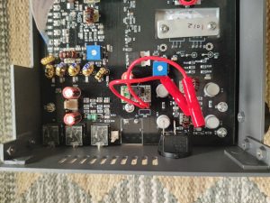
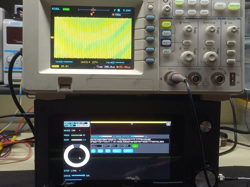
Attach the SWR/Power meter to the sBitx and a dummy load (or an antenna with an SWR of less than 1:1.5 on 80m or 40 meters.
Here is picture of the well calibrated meter. Note that the sBitx power meter on the left is reading 42 watts and the oscilloscope connected across the dummy load is showing 127 volts peak to peak (127v peak to peak across a 50 ohms is 40.3 watts).
For those who live dangerously
The meter calibration is stored at the value bridge in the user_settings.ini file. You will find the file at /home/pi/sbitx/data/user_settings.ini.
The two usual values for bridge are 100 or 72. If your uncalibrated power meter is reporting excessive power compared to the external power meter reading, you can just edit the bridge setting to 70 (if it is at 100).
Check that the values at 20 watts and 40 watts are within a few watts of each other between the sbitx readings and the attached power meter.
The power amplifier gain decreases from 3.5 MHz to 30 MHz. The gain is compensated by decreasing the drive on lower frequencies and increasing it on the higher frequencies. These settings are in the file /home/pi/sbitx/data/hw_settings.ini. In almost all cases, these settings will work for you.
If you would want to recalibrate the drive for each band, this is how it can be done:
The sbitx can automatically run this calibration. Before you do that, you need
Start the sbitx, from the left panel, choose console. In the edit window of console, type txcal and press Enter. The software will trudge along for a minute or so and complete the calibration process.
If the settings get messed up, the there is a backup file called default_hw_settings.ini that you can use to restore the factory defaults.
The sBitx uses a battery backed real time clock(RTC) to keep track of the Coordinated Universal Time even when powered off or offline. This is required for the logbook and the FT8 to work properly.
The UTC maintained by the sBitx is independent of the time reported by the Raspberry Pi’s Desktop/Operating system. The real time clock is accessed and updated only through the sBitx software.
Technical Tip: The sBitx checks to see if the operating system time is synced with the UTC by runnning the ntpstat utility, if it reports that the Raspberry Pi time is synchronized to the UTC, then it copies the current time and date over to the Real Time Clock module.
Each time the sBitx starts, it looks to see if the time is synced and updates the RTC. The code for this in a function called rtc_sync() .
To update the Real time clock properly, you must have the ntp utility working on the Raspberry Pi desktop.
In the terminal, type the following:
In terminal, type:
pi@sbitx:~ $cd sbitx
pi@sbitx:~ $ntpstat
If the ntptstat is working, it will report something like :
pi@sbitx:~$ ntpstat
synchronised to NTP server (164.100.255.123) at stratum 3
 time correct to within 57 ms
 polling server every 64 s
If not, we will have to install three new packages. Enter the following commands:
pi@sbitx:~$ sudo apt install ntp
pi@sbitx:~$ sudo apt install ntpstat
pi@sbitx:~$ sudo apt install ntpdate
After each of these commands, it will ask your permission to download, just press ‘Y’ for yes.
Now, reboot your sBitx from the Terminal.
Now, reboot your sBitx from the Terminal
sudo reboot
When it reboots, reopen the Terminal and type ntpstat again, this time it should synchronize with the network time. It may take a few seconds for the time sync to work, but it usually syncs within a minute. You may have to repeat the command a few times, see the last time of the screen shot below:
The UTC is now working and it will be picked up by sBitx next time it starts.
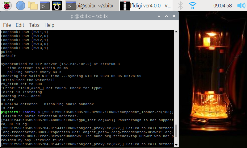
To check this, you can run the sbitx from the terminal with :
pi@sbitx:~$ cd ~/sbitx
pi@sbitx:~$ cd ./sbitx
Note that there is a dot before the /sbitx in the second command. The screen will show a number of messages (most of them are from the Chromium that the sBitx launches). Watch for the messages that says “synchronized to NTP server” and “Reading rtc…done!”. If you don’t get these messages, then the RTC module is not working properly.
See the screen shot below