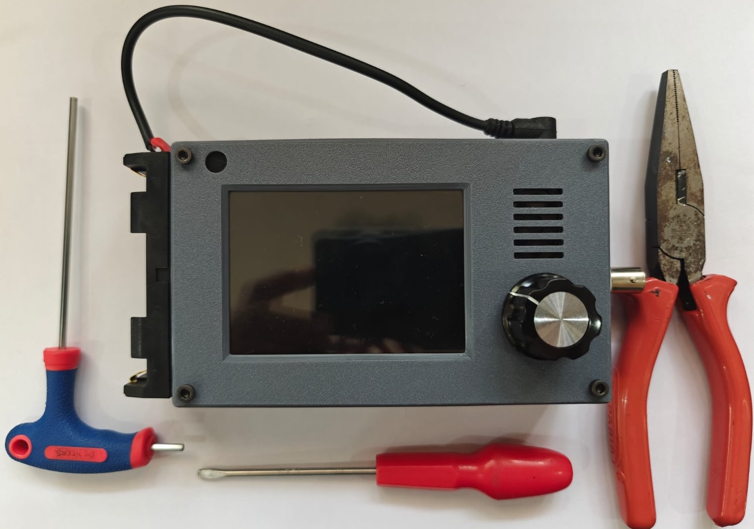
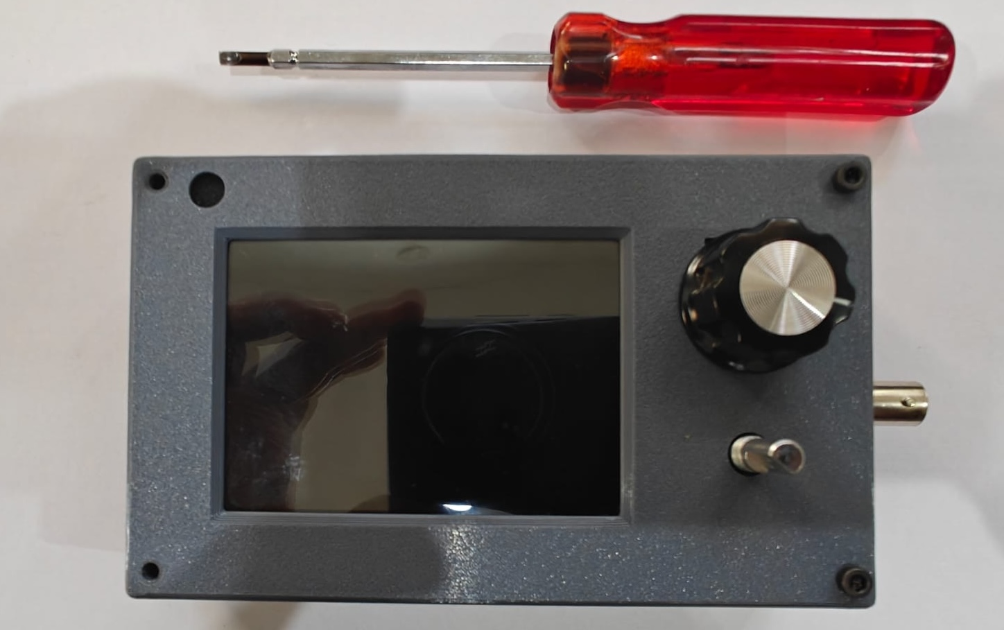
Tools needed: M3 Allen key, Pliers, and slotted head screw driver
Disassembly
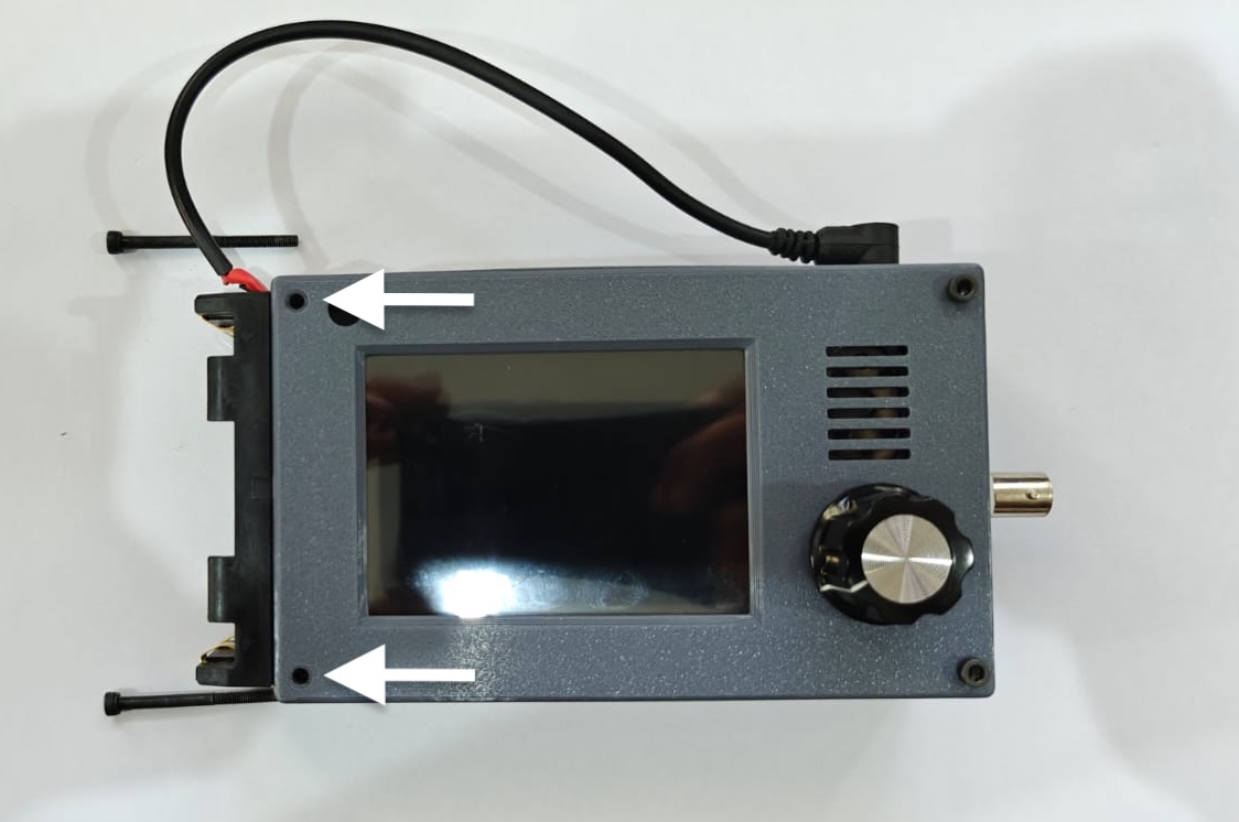
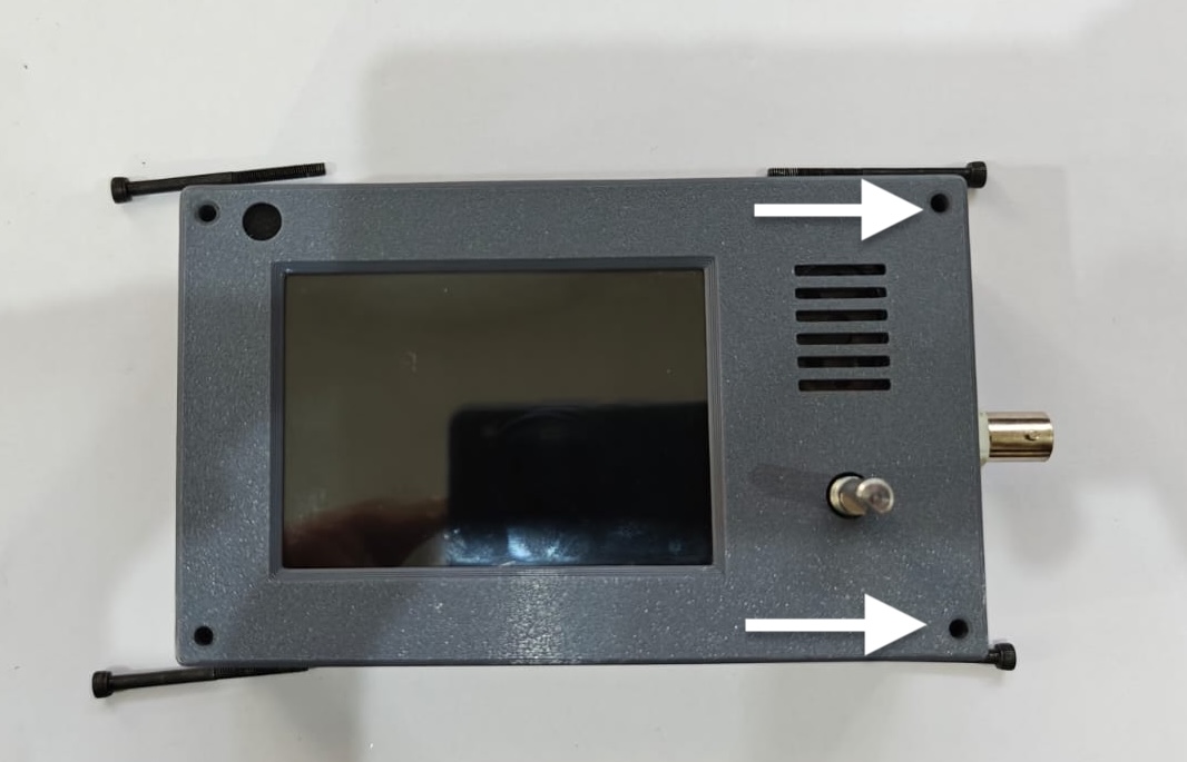
- Remove the bolts near the battery panel, marked with the arrows in the photograph. To do this, grip the nut on the back of the case with pliers or a nut driver and use the supplied Allen key to remove the bolts.
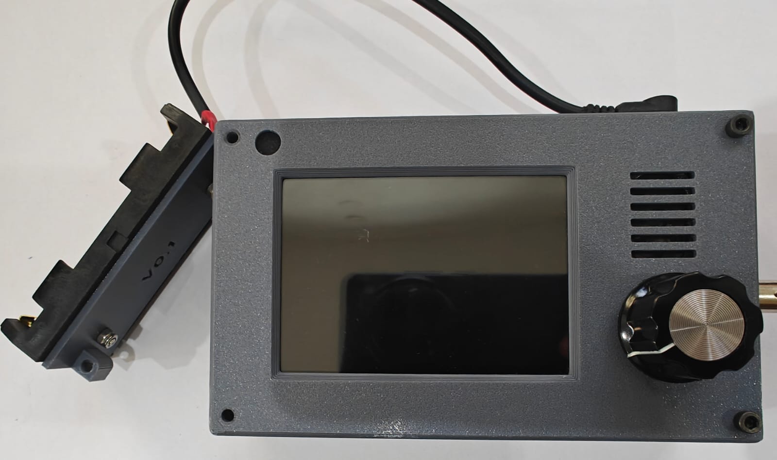
2. Gently pry out the battery panel from the case by pulling the bottom end away from the case.
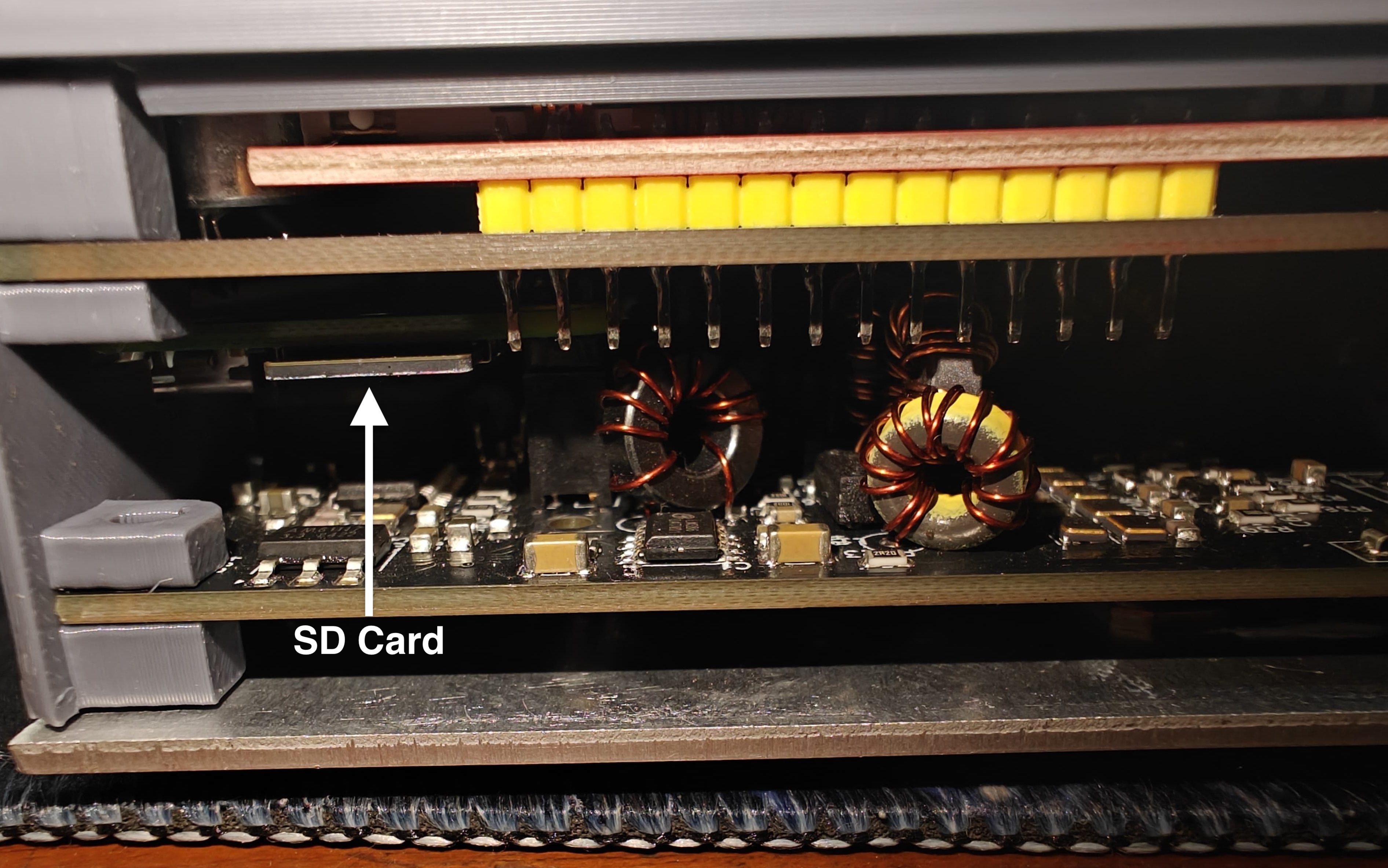
3. If you are planning to replace the microSD card on the zBitx, use a pair of tweezers to grab the SD card out of the slot. Do not proceed beyond this step if you are looking to just replace the SD card.
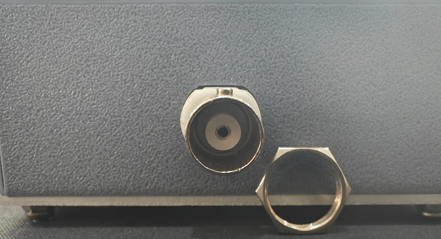
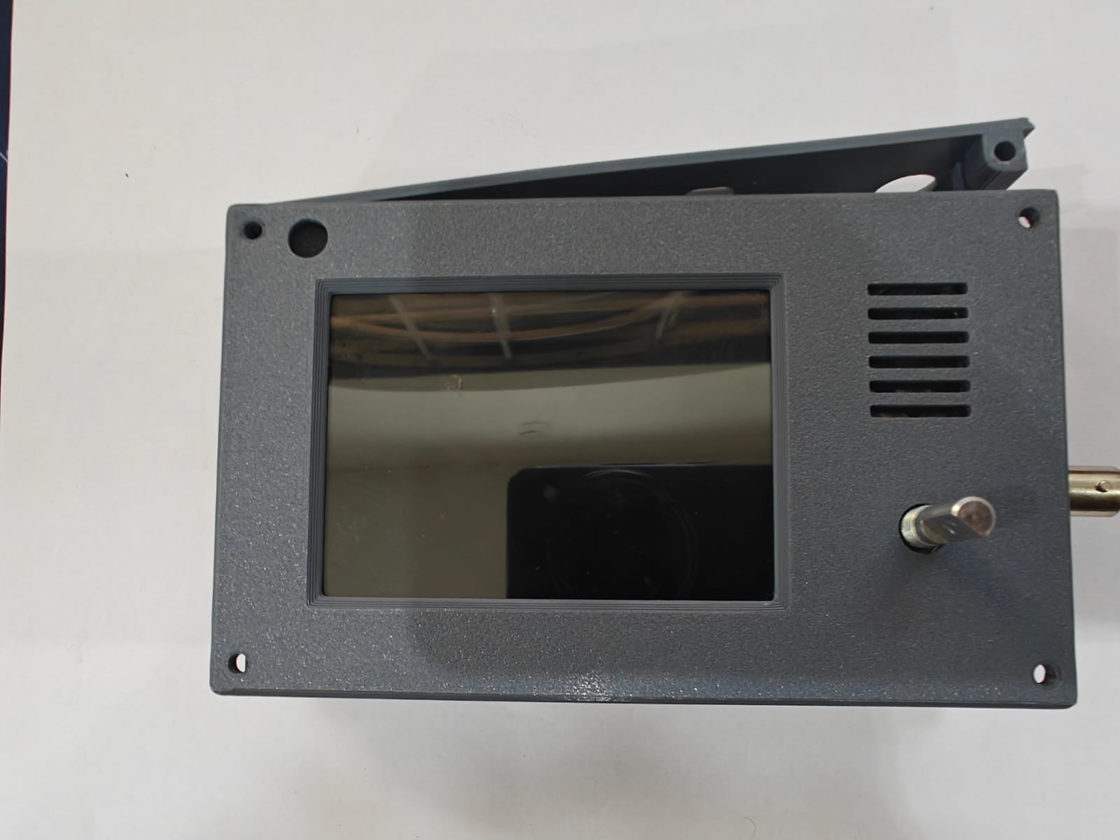
4. To proceed with the disassembly, remove the nut on the BNC connector.
5. If you want to access the front panel, remove the tuning knob by loosening the grub screw using a small head, slotted screwdriver. If you want to access just the main board, you can skip this step. The encoder nut prevents the speaker wires from getting ripped away from the PCB when the case is tilted.
5. Now, remove the two remaining bolts on the BNC connector panel.
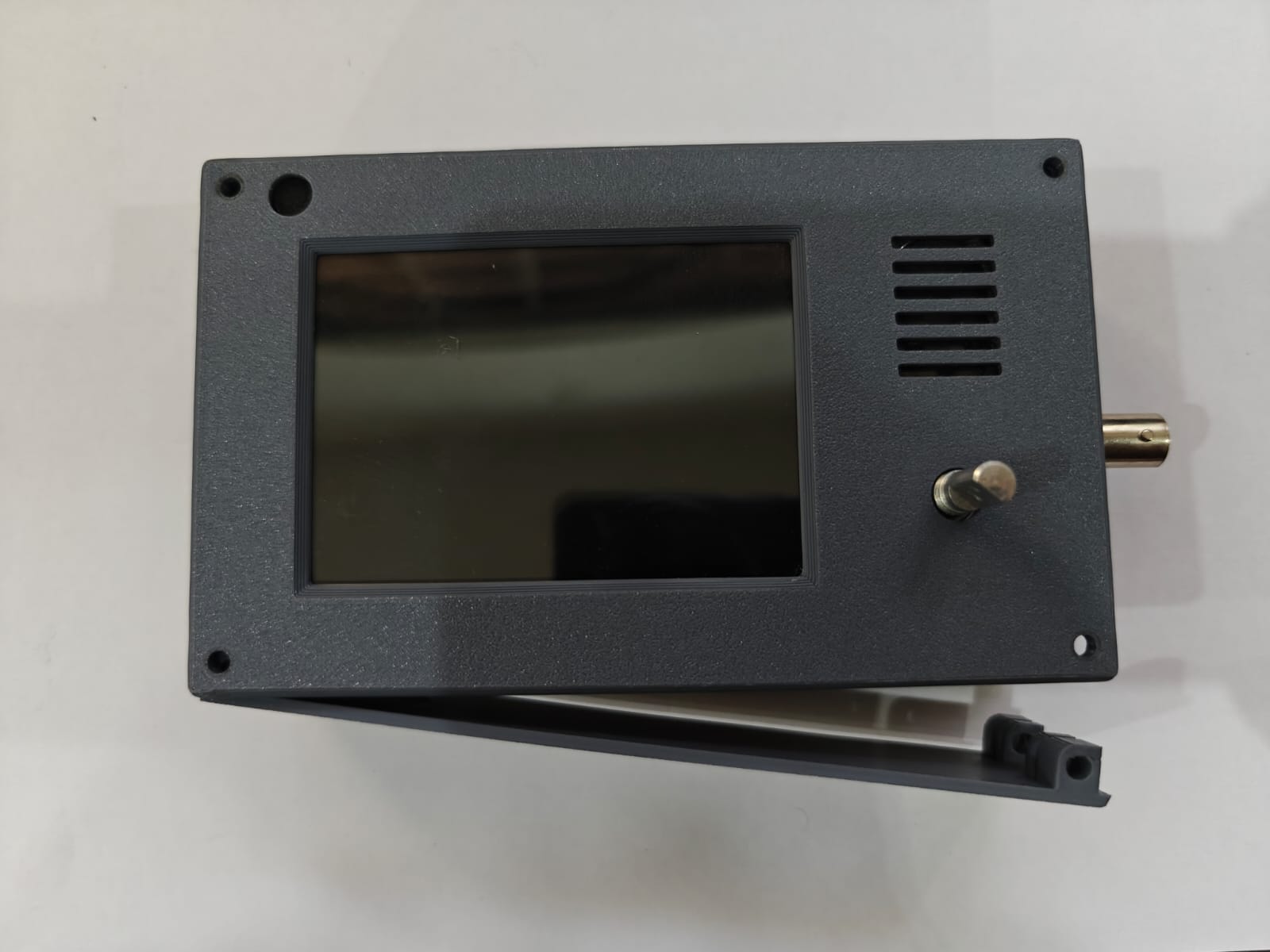
7. To remove the front panel, place the radio on the connector side and the front panel should come off. Exercise caution during this step. If done incorrectly the speaker wire which is connected to the front panel PCB might break. If you are trying to access the main board, you can skip this step.
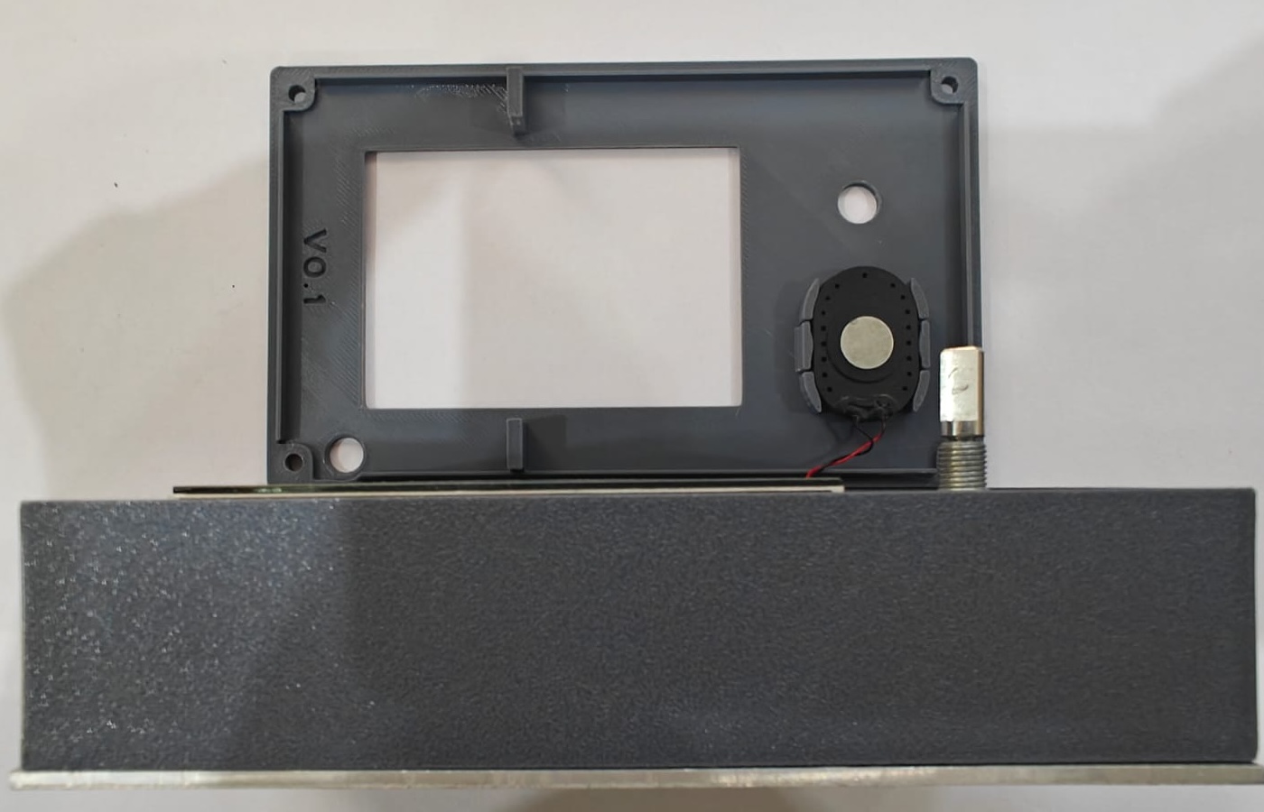
8. Gently remove the bottom and front panel by nudging them out of their position.
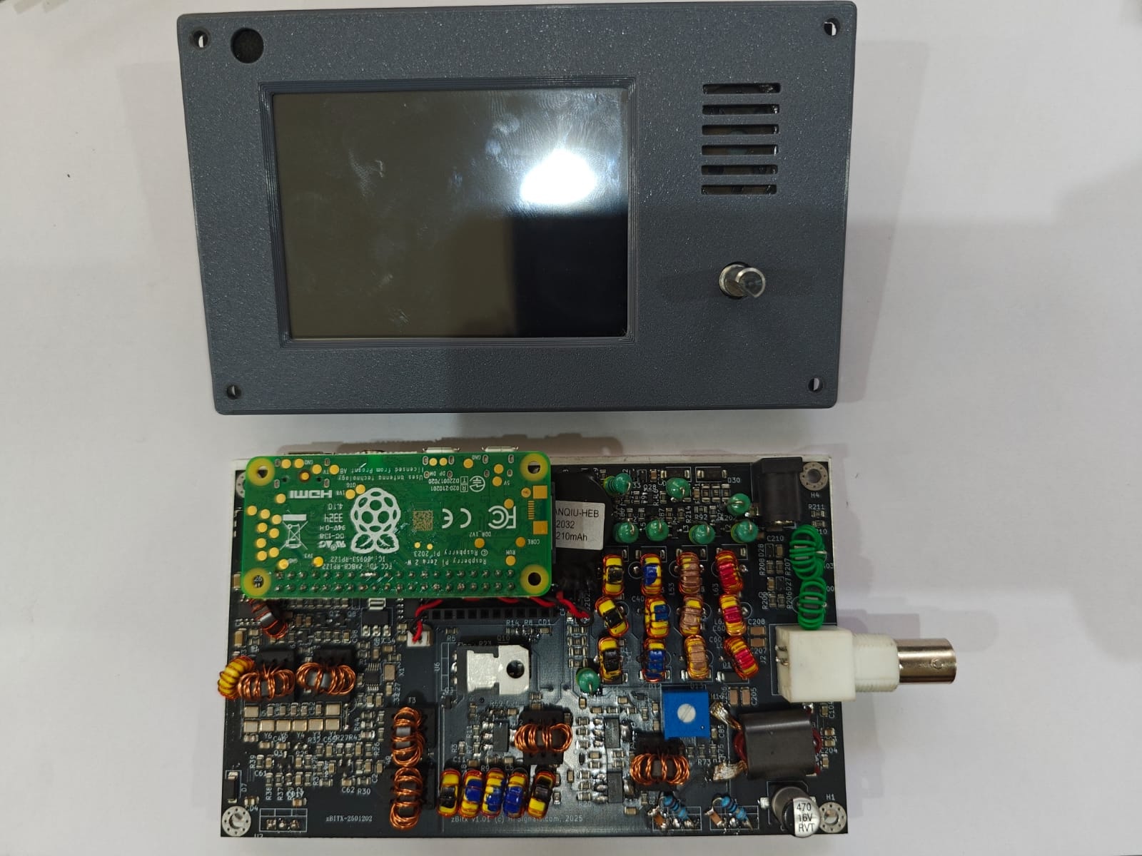
9. To separate the front panel PCB from the main board, gently lift the front panel pcb while holding the main board. This allows you to access the Raspberry Pi Zero and the RF electronics. 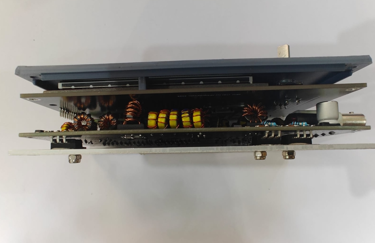
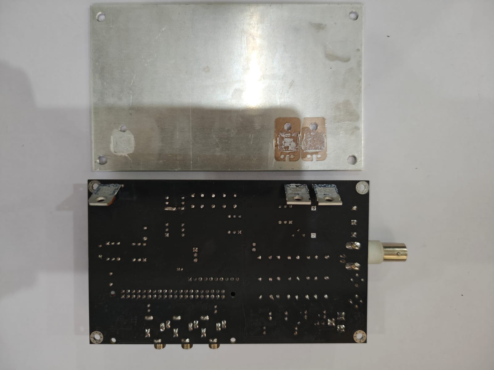
10. To remove the RF board from the heatsink, gently lift the front of the board away from the heatsink plate. Make sure not to lift the board beyond 70-80degrees with respect to the bottom plate or the power amplifier MOSFET and the power regulator might be damaged.
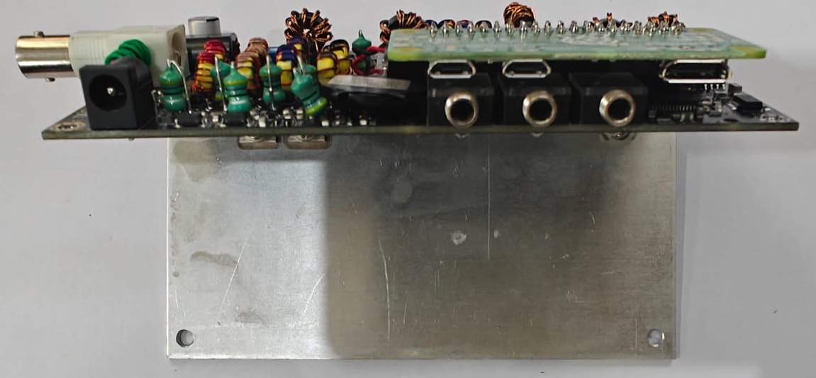
11. Using pliers and a screwdriver (at an angle), remove the nuts on the two MOSFETs and the power regulator. Once this is done, you can separate the board from the heatsink.
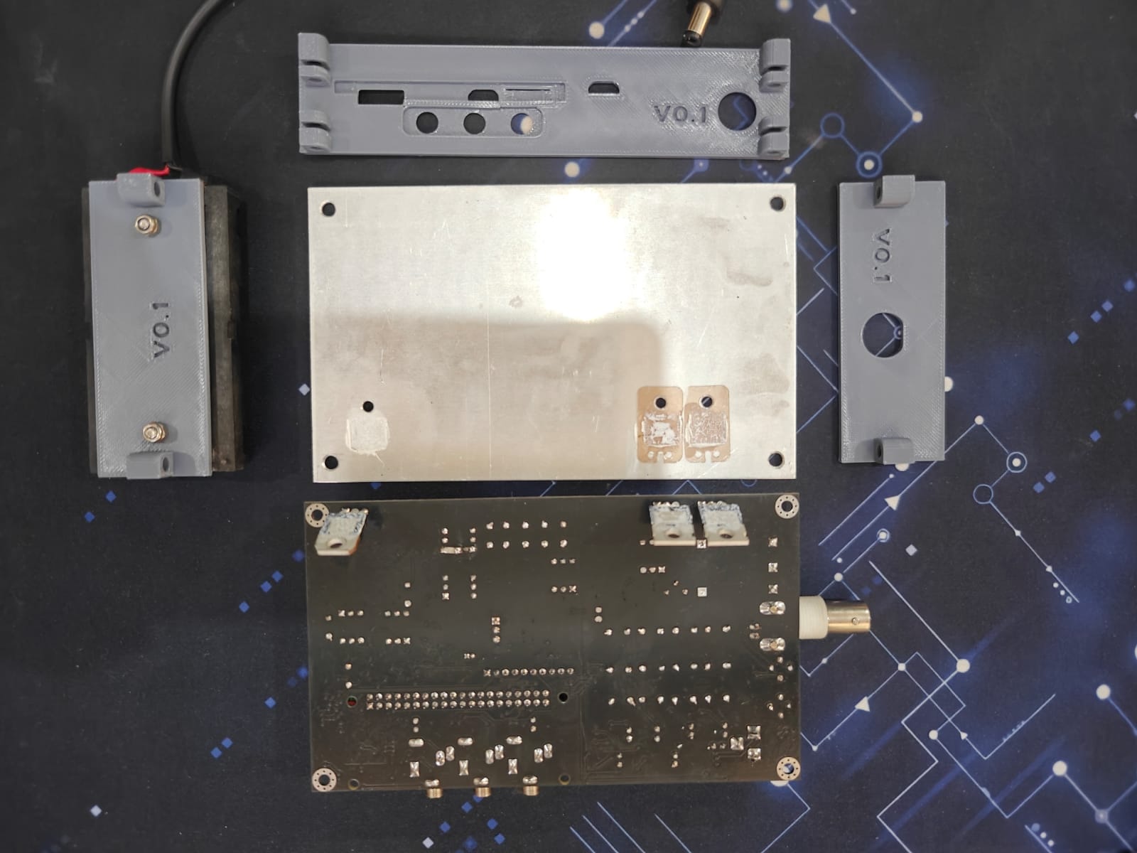
12. To put the radio back together, follow the steps in reverse order. Apply a small amount of heatsink compound on the MOSFETs and regulator to ensure maximum heat conductivity. Proceed slowly and don’t force anything into place. If you break a panel, you can have them 3D printed. The STL files are on the zBitx Github page.