PA sequencing to avoid blow outs
There have been many reports of the PA blowing up. The PA transistor is a MOSFET that can blow up due to high input voltages that can lead to the input gates blowing up or drawing too much current and blowing up the source-drain channel.
What is going on?
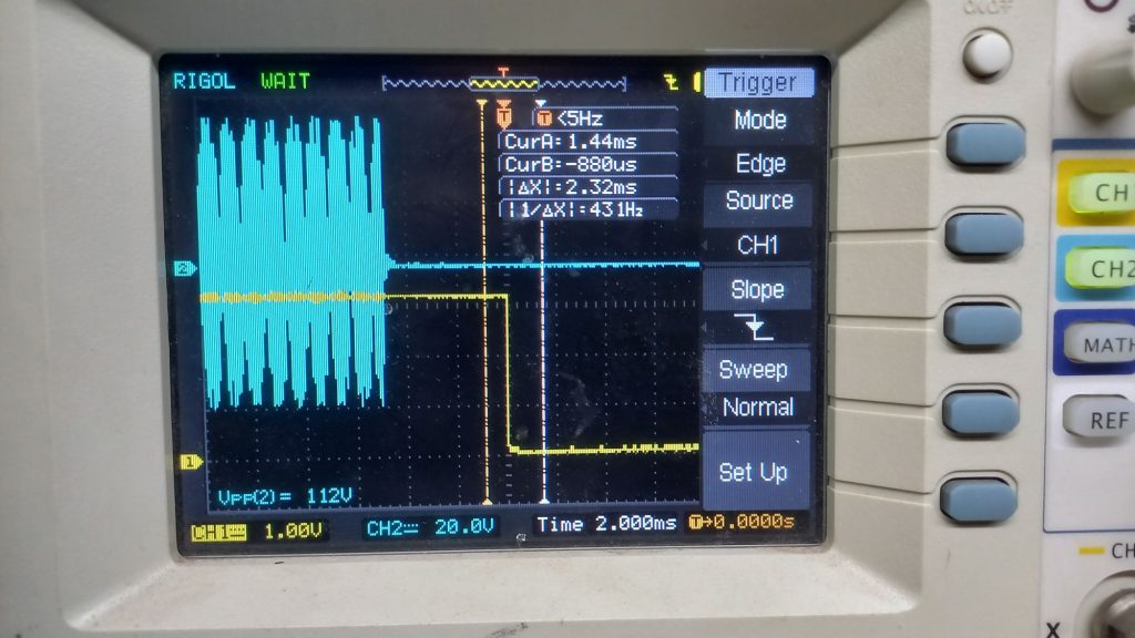
We applied an oscilloscope probe to the TX_LINE. The TX_LINE goes high under raspberry Pi control during transmission. We applied the second probe to a dummy load connected to the antenna socket. What we found is below.
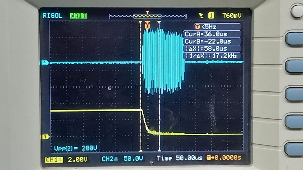
As you can see, there is an enormously high power spike of 220V peak to peak (more than 100 watts of power). Even more telling is that the gate RF t has 20 volts of RF. The maximum rating for the gate is +/-20V as per the datasheet some of the spikes are hitting that as well. See below
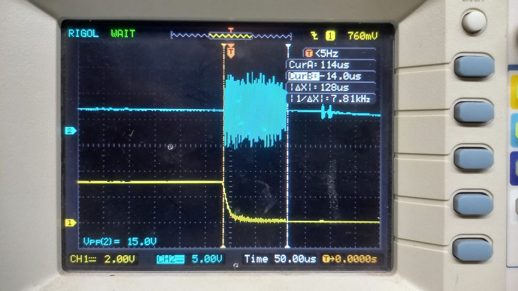
Why is this happening?
The power amplifier is permanently connected between the exciter portion and the harmonic filters. On receive, the power to the drivers and the bias is switched off and the relay K9 with U3 bypass the PA to directly the signal to the rest of the radio.
When the transmission ends, the TX_LINE goes low and the power to the PA is switched off, simultaneously, the relay K9 and the analog switch U3 are released, allowing the RF to flow back from the PA output to the input. The power amplifier takes a few hundred microseconds to power down as the bypass capacitors still hold charge. This sets up the oscillations that we are seeing. To confirm this, I desoldered C14 and the spike went away, (it also renders the receiver dead) by breaking the feedback loop.
The spike of the oscillations remains on for as long as the bypass capacitors of the PA hold charge and they quickly discharge, killing the oscillations. Not quickly enough to do damage.
What is to be done?
The powering up and down of the PA has to be sequenced. When we switch to transmit, we must first switch off the relay and U3, give it a millisecond and then power up the PA. When transiting to receive from transmit, we have to follow the reverse sequence. First power down the PA, wait for the caps to discharge and then switch the relay K9 and the switch at U3 to bypass the PA.
How can it be done?
The PA power is turned on and off in the existing sBitx when TX_LINE goes high at the gate of Q10. Now, instead of the TX_LINE, we take another GPIO line (we can call it TX_POWER) to separately control the powering up and down of the PA. This makes the spike go away.
Four things to do:
- We pull in the new code from github. This software mod does not impact the unmodded sbitx but it can potentially blow up the modified sBitx if this mod is not in place.
Power on the sBitx, open the terminal with Ctrl-Alt-T and type the following:cd sbitx git pull ./build sbitx
- We cut the track that brings the TX_LINE to the gate of the Q10 with a sharp knife.
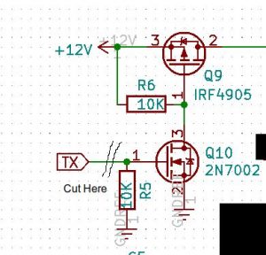
- We add a wire from the Gate of Q10 to be taken to pin 36 of the Raspberry Pi’s connector on the digital board.
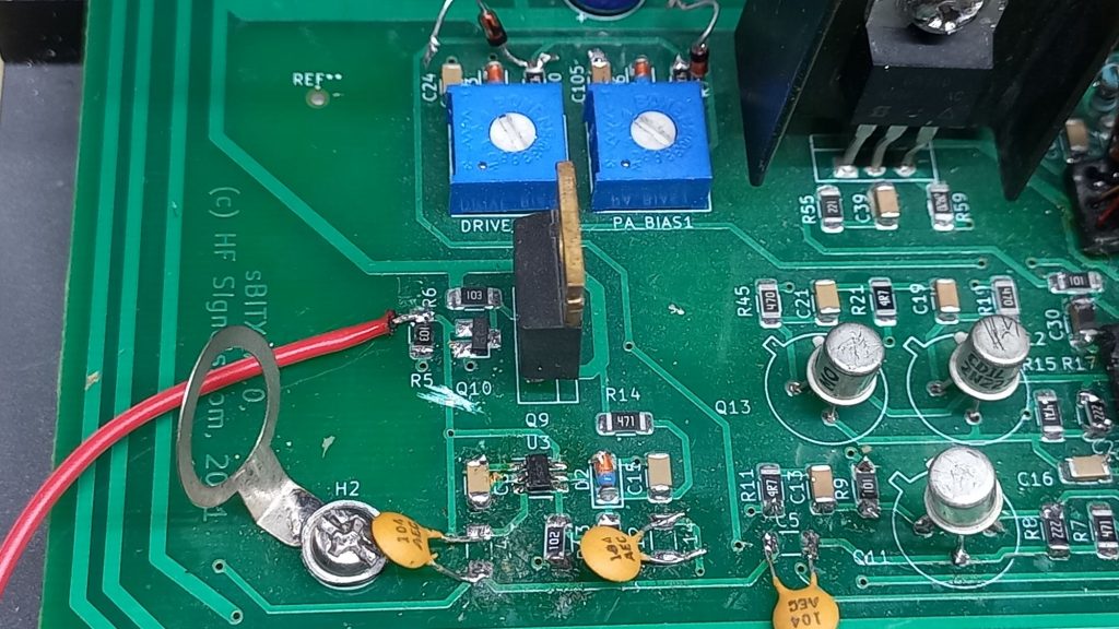
Gate of Q10 isolated from TX_LINE and connected to TX_POWER - We solder the wire coming from the Q10 gate to pin 36 of the Raspberry Pi’s connector on the digital board.
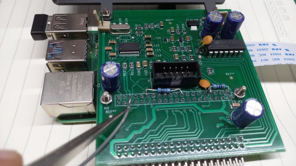
Wire soldered to Pin 36 of RPI to connect to Q10 gate (TX_POWER)
Result
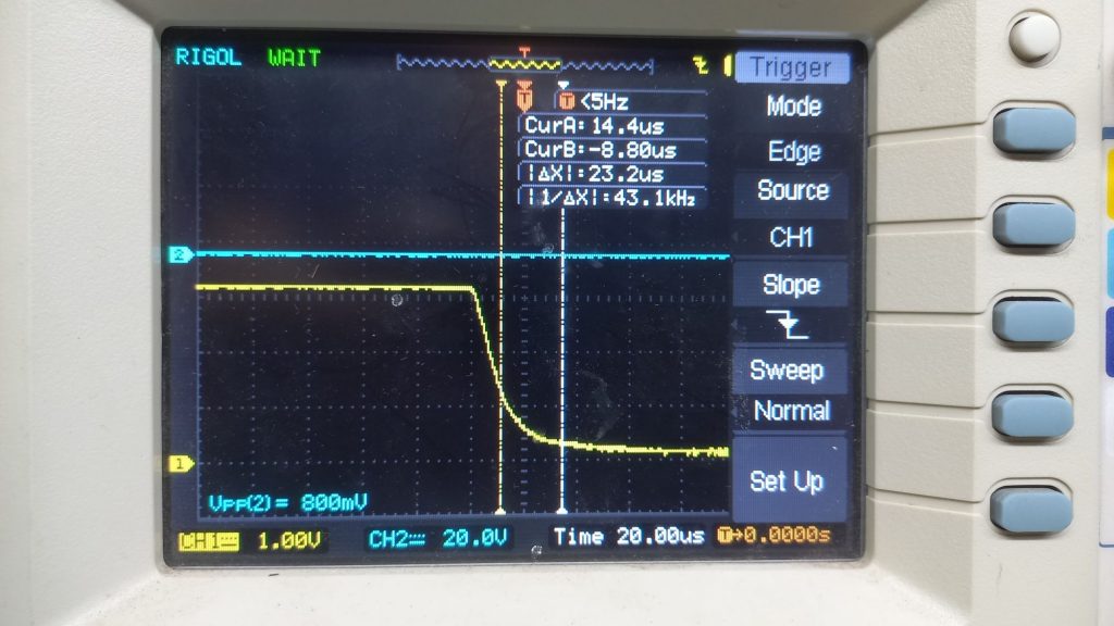
You can see that the spike is gone. The two pictures are taken with different timing bases to be sure.
